


 English
 中文简体
1. Material Selection and Weather Resistance in Outdoor Furniture Choosing the right material is the...
READ MOREIntegrating BESS With Renewables: Sizing, Coupling, and Cabinet Design
Author: Admin
Date: Nov 05,2026
A 40 MW solar plant on a partly cloudy afternoon can fall from full output to a seventh of rated capacity in under three minutes. Nothing is broken; the cloud edge simply moves faster than the plant controller can react. That single behaviour explains most of what a battery energy storage system has to do once it is attached to a renewable asset: absorb the swing, hold the ramp inside the limits written into the connection agreement, and return the energy when the price or the network needs it.
Before chemistry, vendor, or cell format enter the conversation, integration usually succeeds or fails on three decisions: how the storage is coupled to the plant, how power and energy are sized against the real production profile, and whether the enclosure and thermal system will still be doing their job in year fifteen.
Content
- 1 The Interconnection Agreement Sets the Hard Limits
- 2 Sizing Power and Energy Against a Real Production Profile
- 3 How the Storage Sits Inside the Plant
- 4 Wind Integration Asks Different Questions
- 5 The Enclosure and Thermal Design Carry the Risk
- 6 Controls, EMS, and the Handover
- 7 What to Put in the Specification
The Interconnection Agreement Sets the Hard Limits
Every project starts with a document rather than a datasheet. The connection agreement and the local grid code fix the ramp rate the plant must hold, often 10 percent of rated capacity per minute and tighter in weak networks; the frequency and voltage band the storage must ride through; the reactive power it must supply at the point of interconnection; and the delay allowed between a dispatch instruction and a measurable change in output. A system that misses that latency is non-compliant even if every cell is healthy.
This is why sizing begins at the point of interconnection and works backwards. In networks with high renewable penetration the requirement increasingly includes grid-forming behaviour, where the inverter establishes voltage and frequency instead of following them. Ask the network operator early whether grid-following is sufficient, because the answer changes both the inverter shortlist and the control architecture.
Sizing Power and Energy Against a Real Production Profile
Power rating is an obligation; energy capacity is a commercial bet. Take a plant that loses 6 percent of annual generation to curtailment. A two-hour system captures the short clipping events but leaves the long midday blocks on the table; a four-hour system captures both, at roughly double the cabinet count, footprint, and transformer capacity. Run the historical curtailment and price data before fixing a duration, and test the answer against a summer week and a winter week separately, since annual averages hide the shape that actually drives revenue.
| Integration goal | Power-to-energy ratio | Usual duration | Design consequence |
|---|---|---|---|
| Solar ramp-rate control | 1:1 to 1:2 | 15 to 30 minutes | Converter sized near plant rating; fast setpoint tracking |
| Solar energy shifting | 1:4 | Around 4 hours | More cabinets, larger footprint, bigger MV transformer |
| Wind smoothing and compliance | 1:2 to 1:4 | 30 to 60 minutes | Wider state-of-charge window; higher cycle count |
| Frequency response services | 1:0.5 to 1:1 | 15 to 30 minutes | Converter headroom, strict latency, heavier cooling |
Check the C-rate against the cooling design as well. A system specified at 0.5C for shifting behaves very differently when the market asks it to deliver frequency response at 1C in short bursts; the thermal system, not the cells, usually decides how often that is possible.
How the Storage Sits Inside the Plant
AC coupling gives the battery its own power conversion system and transformer on the plant MV bus. Dispatch is independent, the storage can be commissioned before the PV field is finished, and a fault in one system does not take the other offline. The cost is an extra conversion step and an extra transformer bay.
DC coupling shares the PV inverter through a DC/DC converter. It recovers clipping losses, uses one interconnection, and often wins when the grid connection rather than the module count is the bottleneck. The trade-off is tighter coordination, because the hybrid plant controller now divides a single inverter between generation and charging.
Either way, the plant controller becomes the single interface to the network operator, and the cabinets beneath it must accept setpoints at the speed that controller issues them. A liquid-cooled 125 kW cabinet is a common building block in these medium-voltage clusters, since the thermal headroom supports both slow shifting and short high-power events.
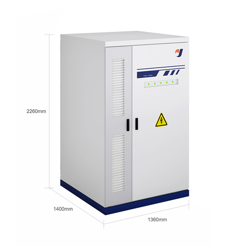 Liquid Cooling Energy Storage System 125kw Energy Storage CabinetThe Liquid energy storage system 125KW Energy Storage Cabinet — a cutting-edge energy storage solution designed for efficiency, reliability, and scalability. Unlike tr...View Product →
Wind Integration Asks Different Questions
Wind behaves unlike solar in two ways that matter for storage. Output is high at night, when prices are low and load is light, and it fluctuates on a timescale of seconds rather than minutes. The battery therefore spends more time smoothing than shifting, cycles more often, and needs a wider state-of-charge window so it can respond in both directions without hitting a limit.
Many wind farms also carry compliance obligations such as voltage support, active power ramping after a gust front, and fault ride-through, which operators would rather meet with storage than with curtailment. A wind-oriented cabinet rated around 100 kW is typically configured for that duty cycle, with the cooling and cycling assumptions set by the gust profile rather than by a daily solar curve.
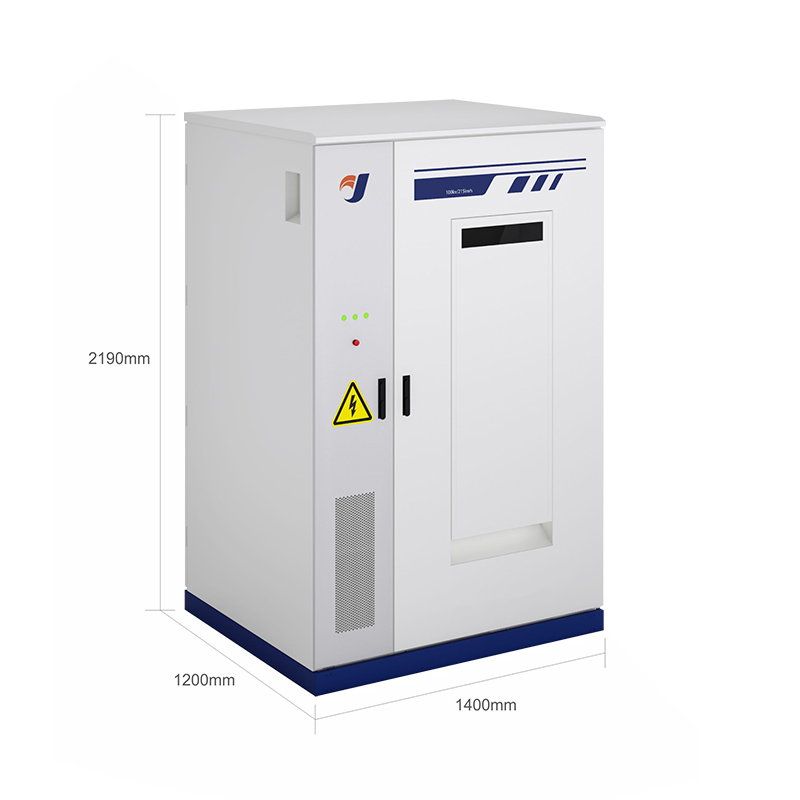 100 kW Air-Cooled Wind Energy Storage CabinetA 100 kW/215 kWh lithium-ion cabinet with air cooling, designed to smooth wind output, support grid stability, and suit scalable commercial or remote deployments.View Product →
The Enclosure and Thermal Design Carry the Risk
Cells are the most reliable part of most systems. The failures that reach warranty claims are usually mechanical and thermal: a gasket that stopped sealing, condensation on a busbar after a cold night, a fan tray clogged with dust in the second summer, a coating that gave up on a coastal site after four years.
For a liquid-cooled cabinet, the number to watch is the cell temperature spread across the rack. Holding it within roughly 3 °C is what preserves cycle life and keeps the battery management system from derating strings on hot afternoons. That spread is set by cold plate layout, coolant flow balance, and how well the cabinet sheds heat at 45 °C ambient with sun on the door.
Mechanical details then decide whether the design survives: IP54 or better, C4 or C5 corrosion protection for coastal and industrial air, a sealed heat exchanger or filtered ventilation, welded frame tolerances that keep doors aligned after transport, cable entries that stay sealed after a technician has been in and out three times, and fire detection that can be serviced without dismantling a rack. Our own cabinet production relies on robot welding, laser-cut frames, and an automatic powder line for exactly these reasons, and the energy storage cabinet range shows how enclosure, coolant routing, and service access are resolved together.
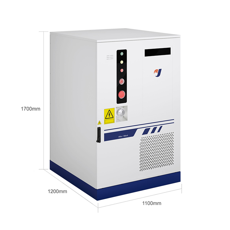 49 kW Liquid-Cooled Commercial Energy Storage CabinetAn all-in-one 49 kW/98 kWh commercial cabinet with liquid cooling, integrated power conversion, and smart monitoring for peak shaving, load shifting, and backup power.View Product →
Controls, EMS, and the Handover
The energy management system is where commercial logic meets physics. It has to respect the state-of-charge window, decide when to charge from the plant rather than the grid, stack services without double-booking the same megawatt, and stop the battery chasing a setpoint it cannot physically deliver.
Commissioning is where most integration problems become visible. The sequence that works:
- Verify communication latency end to end, from dispatch signal to measured output at the meter.
- Test ramp-rate control with a step change, then with the real cloud or gust profile recorded on site.
- Confirm ride-through behaviour by simulating voltage and frequency excursions at the interconnection point.
- Run the thermal system at full power in the design ambient and log the cell temperature spread.
- Hand over state-of-charge calibration, the alarm matrix, spare parts list, and firmware update procedure.
What to Put in the Specification
Most procurement disputes trace back to a specification that described the battery but not the conditions around it. Include at least these:
- Ambient design temperature with solar gain, not just the site average.
- Corrosion category and the coating system that meets it, with a salt-spray test report.
- Required IP rating and the test standard behind the claim.
- Seismic and wind load assumptions for mounting height and foundation type.
- Allowable cell temperature spread at rated power, plus the derating curve above design ambient.
- Factory acceptance test content: capacity check, insulation resistance, coolant leak test, functional trip test.
- Documentation set covering as-built drawings, coolant specification, and maintenance intervals.
Where a standard product does not fit, whether because of an unusual footprint, dual-sided service access, or integration with a specific MV skid, a custom sheet-metal build usually costs less than adapting civil works to a container that was never designed for the site.
The pattern across projects is consistent. Storage sized from the interconnection agreement, coupled in a way the plant controller can actually manage, and housed in an enclosure built for the real ambient and air quality tends to run without drama. Storage bought as a capacity number and fitted afterwards tends to spend its first year in meetings. The engineering order matters more than the cell chemistry.

Contact Us Now
News
LET’S BUILD YOUR CUSTOMIZED PRODUCT

Copyright ©Zhejiang Jiangnan Outdoor Products Co., Ltd.All rights reserved.
